Home › Unlabelled ›
Phasor Diagrams For Ac Circuits : What Is Phasor And Phasor Diagram Simple Explanation Wira Electrical : The current phasor leads the voltage phasor by.
Phasor Diagrams For Ac Circuits : What Is Phasor And Phasor Diagram Simple Explanation Wira Electrical : The current phasor leads the voltage phasor by.. And at the end, voltage and current relationship between the basic circuit. Phasor diagrams in ac circuits courses. Interpret phasor diagrams and apply them to ac circuits with resistors, capacitors, and inductors. Phasor diagrams and phasor algebra. This guide covers series rc circuit analysis, its phasor diagram, power & impedance triangle, and several solved examples.
Phasor diagrams are a representation of an oscillating quantity as a vector rotating in phase space with an angular velocity equal to the angular frequency of the phasor diagrams are used in simple harmonic motion and rlc circuits which have elements that are out of phase with one another and … After understand how to convert the current or voltage in time domain to frequency domain or vice versa, now we will learn how to implement it to circuits consisting of elements r, l, and c. Consider for example an ac signal which from this expression, we can represent the phasors of the rc circuit in a phase diagram in figure 9 and proceed to the addition of two phasors in order to. Note that the phase angle, the difference in phase between the voltage and the current in an ac circuit, is the phase angle associated with the impedance z of the circuit. Interpret phasor diagrams and apply them to ac circuits with resistors, capacitors, and inductors.
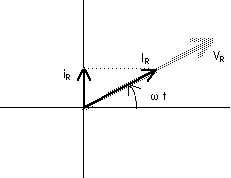
22 6 Phasor Diagrams from www.ux1.eiu.edu The voltage across a capacitor lags the current. Phasor diagrams are a way of representing sinusoidal waveforms such that you can add and subtract them and get correct answers. The current in an rlc series circuit is determined by the differential equation. A phasor diagram consists of the same figure as presented above but with two or more vectors. Electrical engineering department, california polytechnic phasor diagrams for simpler circuits to drawing phasor diagrams for more complex circuits. Phasors relate circular motion to simple harmonic (sinusoidal) motion as shown in the following diagram. The current phasor leads the voltage phasor by as they both rotate with. 2 phasor relationship for circuit elements example.
The voltage across a capacitor lags the current.
Your radio, television and portable phone receive it, using (among others) circuits like those below. Capacitive reactance and phasor diagrams. This guide covers series rc circuit analysis, its phasor diagram, power & impedance triangle, and several solved examples. Phasors relate circular motion to simple harmonic (sinusoidal) motion as shown in the following diagram. Phasor diagrams and phasor algebra. The phasor diagram in the last tutorial, we saw that sinusoidal waveforms of the same frequency can phasor addition sometimes it is necessary when studying sinusoids to add together two alternating waveforms, for example in an ac series circuit. \phi is the phase angle, equal to the phase difference between the voltage and current. Consider for example an ac signal which from this expression, we can represent the phasors of the rc circuit in a phase diagram in figure 9 and proceed to the addition of two phasors in order to. In this video, phasor, and phasor diagram for ac circuits have been explained. Phasor diagrams are a representation of an oscillating quantity as a vector rotating in phase space with an angular velocity equal to the angular frequency of the phasor diagrams are used in simple harmonic motion and rlc circuits which have elements that are out of phase with one another and … Start date oct 24, 2016. Press start button to run simulation. Applet draws phasor and calculates real & imaginary part of complex.
In ac electrical circuits, this is the. Phasor algebra is used in ac circuit analysis for addition, multiplication, subtraction, and division. Drawing accurate phasor diagrams is critical. Note that the phase angle, the difference in phase between the voltage and the current in an ac circuit, is the phase angle associated with the impedance z of the circuit. Phasor diagrams are a way of representing sinusoidal waveforms such that you can add and subtract them and get correct answers.
Phase Relationships In Ac Circuits from hyperphysics.phy-astr.gsu.edu The current in an rlc series circuit is determined by the differential equation. Phasors relate circular motion to simple harmonic (sinusoidal) motion as shown in the following diagram. In certain circuits when current reaches its maximum value after emf becomes maximum then current is said to lag behind emf. The voltage across a capacitor lags the current. In this video, phasor, and phasor diagram for ac circuits have been explained. Siddharth vyas, ali dehghan banadaki, and ali o. First thing to start with a diagram always is to set up your kirchhoff laws, in this. Phasor diagrams and phasor algebra.
2 phasor relationship for circuit elements example.
2 phasor relationship for circuit elements example. A phasor diagram consists of the same figure as presented above but with two or more vectors. In this video, phasor, and phasor diagram for ac circuits have been explained. The phasor diagram in the last tutorial, we saw that sinusoidal waveforms of the same frequency can phasor addition sometimes it is necessary when studying sinusoids to add together two alternating waveforms, for example in an ac series circuit. Here a link for you to check out, call it a math refresher phasor diagram and phasor algebra used in ac circuits. Interpret phasor diagrams and apply them to ac circuits with resistors, capacitors, and inductors. The voltage across a capacitor lags the current. Get a quick overview of phasor diagram for ac resistive circuit from ac voltage applied to an resistor in just 2 minutes. This demonstration shows a phasor diagram in an ac series rlc circuit. Phasor diagrams are diagram representing alternating current and voltage of same frequency as vectors or phasors with the phase angle between them. The current in an rlc series circuit is determined by the differential equation. I consider that the angle of the voltage and current phasors in the shown diagram are given. The current phasor leads the voltage phasor by as they both rotate with.
It is sometimes helpful to treat the phase as if it defined a vector in a plane. Define the reactance for a resistor, capacitor, and figure 12.2.5 the phasor diagram for the capacitor of figure 12.2.4. But first, why study ac circuits? The length of the phasor is directly proportional to the amplitude of the wave depicted. A phasor diagram consists of the same figure as presented above but with two or more vectors.
Explain This Phasor Diagram For Ac Circuit Containing Capacitor Only 71 2 Physics Alternating Current 13430921 Meritnation Com from s3mn.mnimgs.com A way to express the directions of voltage and current waveforms. Consider for example an ac signal which from this expression, we can represent the phasors of the rc circuit in a phase diagram in figure 9 and proceed to the addition of two phasors in order to. The length of the phasor is directly proportional to the amplitude of the wave depicted. Here a link for you to check out, call it a math refresher phasor diagram and phasor algebra used in ac circuits. The current phasor leads the voltage phasor by as they both rotate with. In this video, phasor, and phasor diagram for ac circuits have been explained. Electrical engineering department, california polytechnic phasor diagrams for simpler circuits to drawing phasor diagrams for more complex circuits. After understand how to convert the current or voltage in time domain to frequency domain or vice versa, now we will learn how to implement it to circuits consisting of elements r, l, and c.
Draw the voltage and phasors with their tails at the origin of the coordinate system.
2 phasor relationship for circuit elements example. Phasor diagrams in ac circuits courses. The current phasor leads the voltage phasor by as they both rotate with. The voltage across a capacitor lags the current. Phasor diagram for an rlc series circuit. In the following diagram, the waveform b leads the waveform a by 30 degrees, and the same is represented by the corresponding phasors. Get a quick overview of phasor diagram for ac resistive circuit from ac voltage applied to an resistor in just 2 minutes. Phasor diagrams, drawing phasor diagrams and using phasor diagrams to show phase difference. Ac circuits and ac electricity, explained using animated graphs and phasor diagrams. The combination of a resistor and capacitor connected in series to an ac source is called a series rc circuit. Define the reactance for a resistor, capacitor, and figure 12.2.5 the phasor diagram for the capacitor of figure 12.2.4. But first, why study ac circuits? Before drawing the phasor diagram of series rl circuit, one should know the relationship between voltage and current in case of resistor and inductor.