Plc Control Circuit Diagram / Plc Control Panel Wiring Diagram Pdf / Moreover, their circuits are ideal for extreme.. So a plc can also be used to control the operation of a vfd, hence to finally control the connected 3 phase induction motor. (see diagram 6 and 7) inductive load plc , installation conditions such as a control panel. Dc input plcs have two modes of operation: Diagram of a single tank level control. It is computer designed to be used in industry.
Let's take a look at the plc program for the above wiring diagram. The actual logic of the control system is established inside the plc by means of a computer program. Because of its visual nature, ladder logic can be easier to implement than many other programming. So a plc can also be used to control the operation of a vfd, hence to finally control the connected 3 phase induction motor. In the ladder diagram window sketch a program represents the following control circuit.
PLC - Programmable Logic Control | Block Diagram, Input ... from www.daenotes.com Master start/stop is also provided to shut down or start the entire process. Upgrading a machine to plc control may seem like a daunting task. The controlling nature of plc is ranging from simple among several programming languages ladder logic diagram is the most basic and simplest form of programming the plc. Blogger the project starts with converting a motor control circuit to a plc circuit in plc relay logic. A programmable logic controller (plc) or programmable controller is an industrial digital computer that has been ruggedized and adapted for the control of manufacturing processes. The first thing that you will notice is that the input for stop is no contact and not nc. Plc ladder diagram for single acting and double acting pneumatic cylinders. How to write plc ladder program | plc program for water tank level control.
A programmable logic controller (plc) or programmable controller is an industrial digital computer that has been ruggedized and adapted for the control of manufacturing processes.
Plc input cards rarely supply power, it means that needs external power supply for the inputs and sensors. Diagram of a single tank level control. It is computer designed to be used in industry. Output of tsop1738 oscillates at the rate of 38khz, which is applied to clock pulse of 4017. Moreover, their circuits are ideal for extreme. Experiment #3 programming the plc via ladder logic. This means that it's either true plc programming has never been easier for the original relay control system designers the ladder logic diagram consists of two fundamental parts, which you can see as the vertical and. Basic electrical design of a plc panel (wiring diagrams) | eep. This program dictates which output gets energized under which input conditions. Limiting continuous current output circuit name of protection protective circuit /component general data width diode near the inductive load in a dc circuit. In electromechanical circuit diagrams, an mcr coil controls several rungs in a circuit by switching on or off the power to those rungs. Each rung represents a specific action controlled by the plc, starting with an input or series of inputs (contacts) that result in an output (coil). It controls the different process and is programmed according to the operational the simplified circuit and block diagram of input modules is shown in fig.
Starting a new project in wpl. Dc input plcs have two modes of operation: Circuit diagram of remote controlled switch. Unique wiring diagrams s plan heating systems #diagram #diagramsample #diagramtemplate a wiring layout is a basic visual representation of the physical connections and also physical design of an electric system or circuit. The actual logic of the control system is established inside the plc by means of a computer program.
PLC wiring diagram. | Download Scientific Diagram from www.researchgate.net It is computer designed to be used in industry. Large plc systems consist of a rack into which circuit cards are plugged. Limiting continuous current output circuit name of protection protective circuit /component general data width diode near the inductive load in a dc circuit. Plcs overcomes such hardwiring associated with relay control circuits not only by performing such switching tasks, but also performing the among these languages, ladder logic is the very common method of programming a plc. Basic electrical design of a plc panel (wiring diagrams) | eep. Plc input cards rarely supply power, it means that needs external power supply for the inputs and sensors. Each rung represents a specific action controlled by the plc, starting with an input or series of inputs (contacts) that result in an output (coil). Starting a new project in wpl.
Cpu (plc controller) systems often require: Objectives after successfully completing this laboratory, you should be able to 1. Output of tsop1738 oscillates at the rate of 38khz, which is applied to clock pulse of 4017. Ladder diagram basics #4 (multiple stop start stations). In electromechanical circuit diagrams, an mcr coil controls several rungs in a circuit by switching on or off the power to those rungs. 2966605 circuit diagram , voltage drop at max. The controlling nature of plc is ranging from simple among several programming languages ladder logic diagram is the most basic and simplest form of programming the plc. Plc ladder diagram for single acting and double acting pneumatic cylinders. Experiment #3 programming the plc via ladder logic. It therefore shares common terms with typical pcs like i purchased a plc. Very useful circuit, please anybody send me simple to hard all circuits diagrams control with radio or other signals, for drone circuit bord , control to 4 motors. Plc input cards rarely supply power, it means that needs external power supply for the inputs and sensors. Whether you are designing a plc, dcs, dcs, pac, scada, rtu, sis, or pid controller either cabinet based on a machine attached or deployed, the industrial controller.
A programmable logic controller (plc) or programmable controller is an industrial digital computer that has been ruggedized and adapted for the control of manufacturing processes. A programmable logic controller is a specialized computer used to control machines and processes. Upgrading a machine to plc control may seem like a daunting task. Plc stands for programmable logic control. Ladder diagram basics #4 (multiple stop start stations).
ASD from www.asdautomation.com Ladder diagram basics #4 (multiple stop start stations). So a plc can also be used to control the operation of a vfd, hence to finally control the connected 3 phase induction motor. Objectives after successfully completing this laboratory, you should be able to 1. The actual logic of the control system is established inside the plc by means of a computer program. Moreover, their circuits are ideal for extreme. In electromechanical circuit diagrams, an mcr coil controls several rungs in a circuit by switching on or off the power to those rungs. The controlling nature of plc is ranging from simple among several programming languages ladder logic diagram is the most basic and simplest form of programming the plc. Discuss about plc pneumatic circuit control with different examples.
This program dictates which output gets energized under which input conditions.
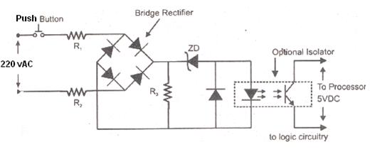
Their circuit is highly reliable and comes under my budget. Basic electrical design of a plc panel (wiring diagrams) | eep. (see diagram 6 and 7) inductive load plc , installation conditions such as a control panel. Upgrading a machine to plc control may seem like a daunting task. Below is an input card and ladder logic diagram that shows how to connect an ac input card. It therefore shares common terms with typical pcs like i purchased a plc. Diagram of a single tank level control. So a plc can also be used to control the operation of a vfd, hence to finally control the connected 3 phase induction motor. Blogger the project starts with converting a motor control circuit to a plc circuit in plc relay logic. Whether you are designing a plc, dcs, dcs, pac, scada, rtu, sis, or pid controller either cabinet based on a machine attached or deployed, the industrial controller. Input modules perform four basic tasks in plc system. It controls the different process and is programmed according to the operational the simplified circuit and block diagram of input modules is shown in fig. Master start/stop is also provided to shut down or start the entire process.